
The following document describes how the oil system should be setup on a FR ProStreet kit. There are two major parts to the oil system, the feed and the return. On bushing turbochargers, the oil system is extremely important. The oil serves two purposes, it lubricates and cools down the bearings within the CHRA. If not installed properly, a poor oiling setup can cause turbocharger and or complete engine failure. Also, clean oil is a necessity on a turbo system. We recommend a inline oil filter whenever feasible.
This will provide you with extra insurance of supplying the turbocharger with clean filtered oil at all times.
Feed
The turbocharger oil feed is supplied from the oil pressure sensor port on the back of the block. This is setup with the included BSPT, NPT fittings, and -3 AN line. PTFE tape is required on all fitting junctions except for 37 deg. AN connections. It is also highly
recommended to clean the block and lines before installation so that leaks can be easily detected.
1. Clean area on the block around the oil pressure sensor.
2. Remove the oil pressure sensor.
3. Install BSPT fitting into the block.
4. Install 1/8 in. NPT “T” into the BSPT fitting.
5. Install oil pressure sensor into NPT “T”.
6. Install 1/8 in. to -3 AN adapter into NPT “T”.
7. Fasten -3 line to -3 fitting.
8. Run line from the back of the block to the turbocharger. Route line so that it clears all moving parts and heat sources.
9. Install oil inlet fitting onto the turbocharger.
10. Fasten -3 line to the turbocharger.
Drain
The turbocharger oil drain is returned to the oil pan. We recommend mounting the supplied -10 mild steel bung as high as possible on the pan. Also, the oil drain line must not be kinked at all. The bend should have a large smooth radius whenever possible. This will prevent “backing up” and will ensure proper draining.
1. Drain oil.
2. Remove pan.
3. Clean pan.
4. Prep pan for welding.
5. Fabricate -10 line from the turbo to the pan.
6. Determine position of the -10 mild steel bung.
7. Tack bung.
8. Test fit pan and oil return line.
9. Reposition if necessary.
The following pictures illustrate a properly installed oil drain line.
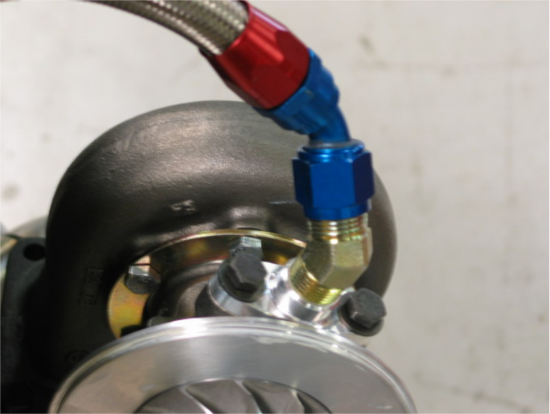
Figure 1.CHRA oil drain fittings
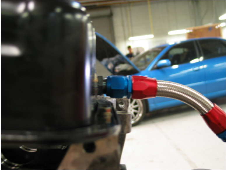
Figure 2.Oil drain line
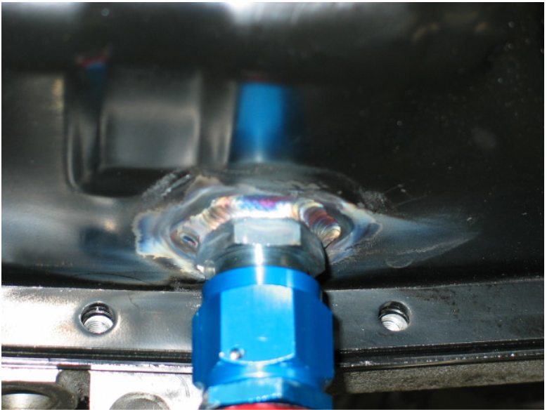
Figure 3. -10 mild steel fitting
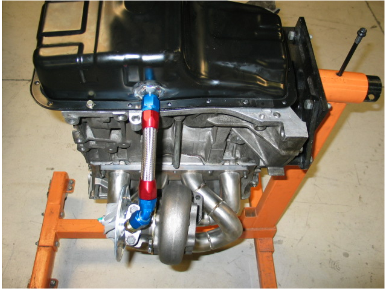
Figure 4. Top view of the installed system
Post time: Jun-26-2023